Tuesday 25 October 2011

Week 6

This week I have been experimenting with the different types of lights, and ways to get animations to looks visually realistic with lights. The first light that I experimented with was the daylight light. The daylight light is good if you want to get the lighting and shadowing to resemble a certain time of year. You pick what area of the world you want. where north, east, south and west are. And the time/date. This light would mainly be useful for architecture.

The second light that I experimented with was the target spotlight.  The spotlight emits light in a forward position like a flash light. The spotlight would be good for touches, or car headlight in an animation.
The last experiment was with the Omni light. The Omni light emits light from all directions like a sun. In this scene there are two Omni lights. One of them is only affecting the sky dome, while the other one is affecting everything part from the sky dome. The second light is also emitting a reddish tint to it.

Monday 24 October 2011

Week 5

The task for this week was to unwrap an object with Unwrap UVW ,then edit  it in Photoshop. Once I applied the Unwrap UVW, I selected all the faces then clicked edit. A new window popped up but I needed to sort the faces out, so I know what ones are which. I did this by flatten the image then Selecting each face then moved them. I then rendered the image then saved it.
I open the image in Photoshop and did some editing on a new layer. Once I was done I saved the image then imported it to 3ds max.
I applied the image to the box and it warped around perfectly.

Sunday 23 October 2011

Princess Leia's ship

The animation takes place in episode 4 on Princess Leia’s ship. I used clips from the film to get an overall feel of what the ship looks like. I started off by making the walls and supports. I used the Line and Arc tools to make the outline of the wall. I used the Extrude modifier to make the Spline 3D.


The support is nearly the same shape as the wall, part from the top is a bit different.


I copied the walls and supports around the floor. I used the Align tool to align the supports and walls together.


With Auto Grid selected I made some shapes on the support to look like control panels. The spheres are very low poly, this will not be noticeable during the animation, as there will not be any close ups of the control panel.


 I decided to keep the corner of the corrie door simple, because when R2D2 hits the wall using the curved bottom would flip R2D2 over. I don’t want that so I chose to keep the walls straight.


All the walls have sections that are pulled out or pulled in. I did this with the Bevel tool. From my research each wall had a different layout of sections pulled in and out. I pulled each section in and out at random, but kept the same distance of how much they were pulled.


I added some extra edges to the walls then used the Extrude tool, to push in some holes on the walls. Some of the walls had some control panels connect to them like the support. I modelled them the same way I modelled the ones for the supports.


 I added a ceiling and made an indent in it with the Insert and Extrude tools. This should be enough room to do that animation in. But if I need more room I can just copy some of the walls and supports over.


Monday 17 October 2011

R2-D2 Model

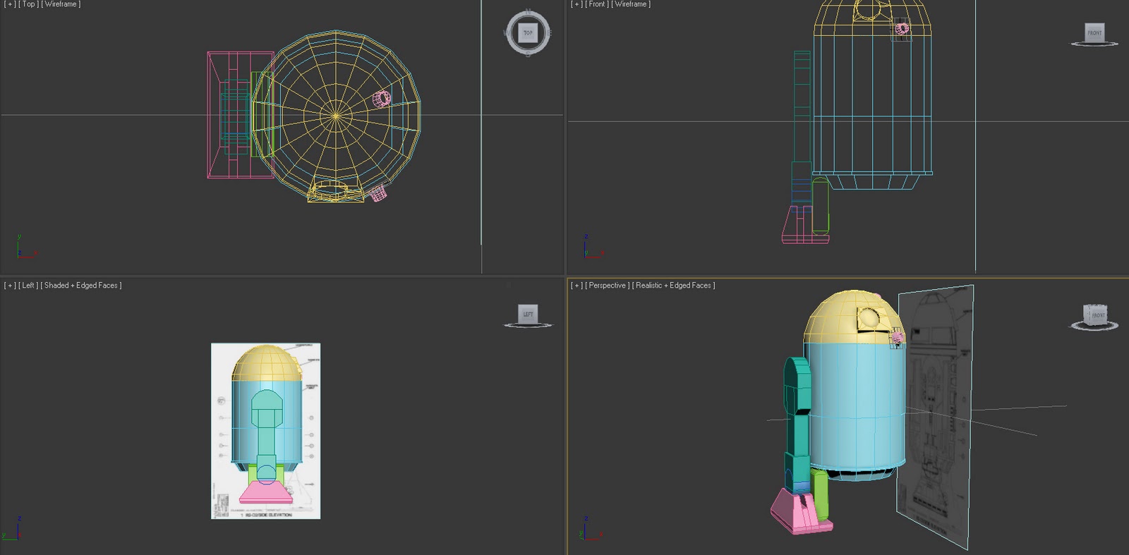
R2D2's body is made from a cylinder. I used the Insert and bevel tools on the bottom of R2D2, to bring the edges in slightly. I changed the position of 3 side vertices on each side, so the sides don’t lean out from their top vertices. so when I create the legs they will not go into the body. The head is made from half a sphere using the Hemisphere parameter. The reason why the head is not connected to the body, is because it will be animated and I don’t want to move the vertices that would have been connected to the body.
The leg is made from a cylinder connected to a rectangle. I did this by making a cylinder and a box, then turning both to an edible poly. I select the cylinder and deleted most of the bottom half polygons. I then selected the rectangle and deleted the top polygon, so I could weld the two objects together. I  welded the objects together by attaching both of them, then using target weld, to weld the vertices together. I then extruded the bottom part of the square to make the rest of the leg. For the foot part, I used a square then moved the edges to match the template. I added two lines down the middle of the foot, then one round the side so I could extruded the middle part downwards.
I added a couple of lines on the head part of R2D2, so I could extruded the polygons to model the eye. I then made a cylinder with the Auto Grid selected, so that the bottom of the cylinder is aligned with the newly extruded eye. I moved the cylinder in a bit using the local setting. Then Boolean the cylinder for the head to make a circular indent. When I did this the circle area of the eye was made but, I could see right though to the over side of the head. I filed in the hole with the create tool by selecting each vertex where the hole was. I found out that R2D2 had 3 cameras around its head, I model them by using the auto grid option so I could place a cylinder on the head. I used the insert tool to make some inner edges then used the bevel tool to extrude them out and pull them inwards. For the green box under the body, I used a cylinder then selected the top vertices then pulled then up.
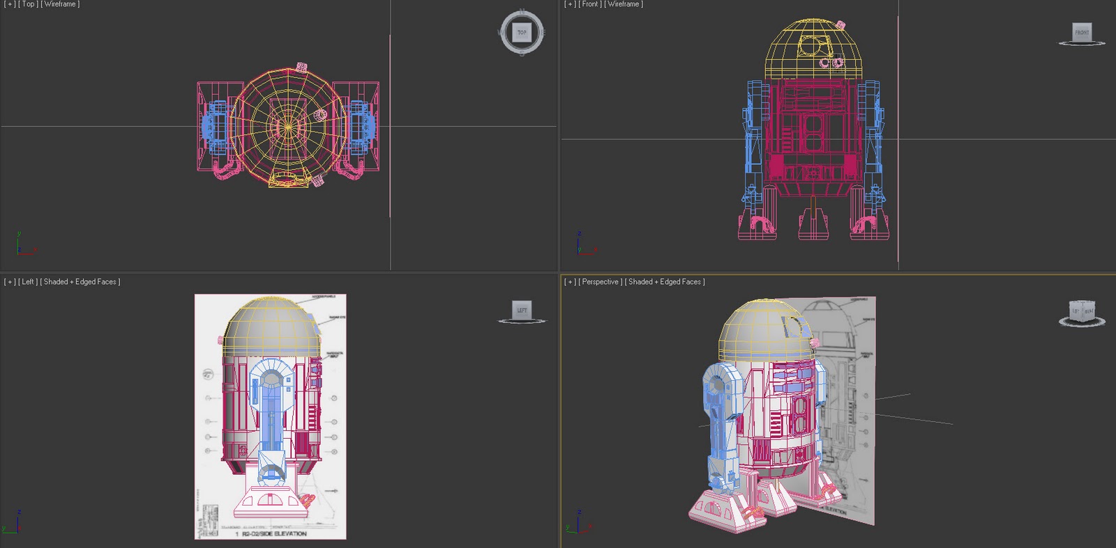
At this point I Had to made a decision about how I will put the detail into the R2D2 model. If I was using the model for a game, then I would try to keep my poly count down, and used materials and bump maps to put the detail in. But as I’m doing this for an animation I don’t need to worry about that to much, but it might take a bit longer to render. I added the front bits of detail in by adding more edges and extruding them. I don’t want to go into much detail how I did every little bit as I’ll be repeating the same thing over and over.
I added more detail to the front of the body by adding edges and extruding them. It took some time but I believe that when I have lights in my scene, the small bit of shading around the body will probably be quite effective. I made some wires for the feet by using cylinder. I extruded the top polygon then rotated it slightly, then extruded it again. I repeated this pattern in till I got to green box.
There is not really a lot I can say here, part from I added some detail to the back of the body the same way as I did for the front.
I used the insert tool on the top and middle section of the leg. I selected the middle section and divided it into 3 section by adding in some edges. I extruded both of the side polygons on the middle section, so I could place a cylinder in the indented middle part. The pink cylinder in the leg is made by adding two edges on the cylinder then extruding the polygons in-between them.
With the bottom part of the leg I Boolean it out with a cylinder then attached another cylinder to it, then target welded the vertices. I made some small shapes for the leg to match the ones found on R2D2. I used the attached tool so they became part of the leg.
I added some shapes to the foot using the attach tool and auto grid so they are aligned. There are some complexes shapes on R2D2 that I could not do by adding edges. So I made the shapes then Boolean them from the body. After I Boolean then, the model had some extra edges added. I was thinking of removing them to make it neater, but it could cause the body to lose a bit of its round shape so I dropped the idea.
With the model almost finished I need to create R2D2's extra foot that appears when R2D2 is moving. I created the foot the same why I created the others, but this one was a bit smaller.
I Selected different polygons then applied materials to it. There materials are not the final ones, but they are just there so I get a feel of what the final result might look like.
Just 4 different angels of R2D2.
A high res image of  R2D2.

Mouse Droid Model

I could not find any relevant images of a mouse droid to use as a template. I decided to sketch my own using some images from Google as reference
(http://images.wikia.com/starwars/images/b/b7/MSE-6_btm.jpg).
I started out with a box then extruded it downwards. I selected the side edges and added 4 new lines using the connect tool. I selected the polygons that the added lines made and extruded them out. I selected the top and bottom and used the select and uniform scale tool, to make the edges lean into each other.
I added lines on the side of the body with the connect tool to make a square. In the square I added 8 columns & 11 rows of lines to make little squares in the big one. I selected some of the polygons then used the bevel tool to extrude them out, then bring them in slightly to make a gap between each one. With the leftover gaps I used the Insert tool twice then used the extrude tool.
I created a rectangle on top of the mouse droid’s body with the Auto grid selected, so that the rectangle will sit on top of the body. I also used the Auto Grid for the cylinders sitting at the top.
With the line going down the middle of the droid, I deleted half of the body that does not have the detail on. I then used the Symmetry modifier to mirror the side across. I then converted the droid back to an editable poly.  For the wheel I used a cylinder then Boolean it from the droids body to place the wheels. The wheels are made from a cylinder. I used the Insert and extruded tool on the wheel to make the rims. The wheel are not connected to the body because they will probably be turning in the animation.

Vader Model

In one of the scenes in the animation Vader’s shadow is cast over R2D2. To get this effect I'm planning on having a light behind a cut out of Vader that will casts a Vader shape shadow. I found a front view template of Vader from (http://images.wikia.com/starwars/images/7/74/Vader_blueprint.jpg).
I started by using the line tool to draw a straight line right down the middle of the template. I plan to use the mirror modifier for the other half, so I only need to make one side of the model. I went around the template with the line tool roughly, in till I could close the circuit. I then zoomed in on each vertex and moved them in to a better position. For the curved edges on the temple, I used the fillet tool to make the edges curved.
I applied the mirror and extrude modifiers to make the other half of Vader, and to make it in to a 3D object so it can block light to cast a shadow. I converted the shape into a editable ploy, so I could connect the two half’s together with target weld.

Week 4

The first task for this week was to make two materials that look like they are made out of wood and metal.
The first material is wood.  The material has a low secular level and glossiness because wood is not shiny like metal.
The second material is metal. The secular level Is much higher as it makes the metal looks more reflective. If I put the glossiness up to high I end up with more of a plastic look so I kept it low, but higher than the glossiness I used for the wood material.
The next task was to experiment with the different procedural maps. The good thing about procedural maps are that they never lose resolution unlike bitmaps, but you cant put as much details in to the materials unlike bitmaps.
When materials are applied on different shapes they don’t tile up, and the materials gets stretch.
Sphere-BOX mapping: The Image is trying to apply it self to a 6 sided shape, but as the sphere is round the sections are overlapping each other.
Sphere-SPHERICAL mapping: The images is warped around the object, so the sides meet from the top of the sphere all the way to the bottom. As the images is lighter on one side you can see the line going from the top to the bottom.
Sphere-SHRINK WRAP: All of the corners of the image meet at the bottom part of the sphere.
Cylinder-CYLINDER mapping:  Warps the image around the sides.
Cylinder-CYLINDER mapping with CAP: Warps the image around the sides, but also adds the image on the top and bottom faces.
Teapot -FACE mapping: Maps the image on every polygon of the shape.
Teapot-SPHERICAL mapping: I found that the spherical mapping on the teapot was the best choice to have the image warp around the object.
The last task for this week was to make a cloud material using procedural maps. The material is made out of two procedural maps, combined with a mask to make some transparent holes. This material would be also good for smoke.

Monday 10 October 2011

Week 3

This week we learnt about the lathe modifier, an how we can save time by using it. I modelled 4 different chess pieces all using the lathe modifier, although some extra work was required on each of the pieces. Using the line tool I went around half of the outline of the chess pieces. I then converted the line to an editable spline, so I can make certain section curved using the fillet option. I then applied the Lathe Modifier to rotate the line in a 360 angle to make the sides circler. 

For the Castle: Extruded different polygons at the top.
For the Bishop: Used a boolean to subtract a chunk from the top.
For the Queen: Extruded different polygons at the top.
For the King:  Added a cross shape at the top.

Using the box modelling  technique I made a jet plane. I started off with a cylinder an added more edges when needed, while using the Select and Uniform scale to change the shape. I  Extruded some polygons to model the wings and the back of the plane. I used the symmetry tool to get both sides to look the same.

Monday 3 October 2011

Week 2 small derelict village

I created a basic outline for the 3 building and the water fountain with the shape tool. The 3 building are a church with a bell and clock, a two story house and a mansion.
Using basic 3d shapes like boxes and spheres, I used the Inset, Bevel and extrude tools to build inner an outer walls of the buildings. I added extra vertices when need to get the shape I wanted. For the bell part of the church I used the align tool to align the bell to the top of the church.
I changed some of the vertices of a sphere to get a rock/bolder shape, then booleaned it form the buildings to make it look like its been destroyed over the years.